Electric motor
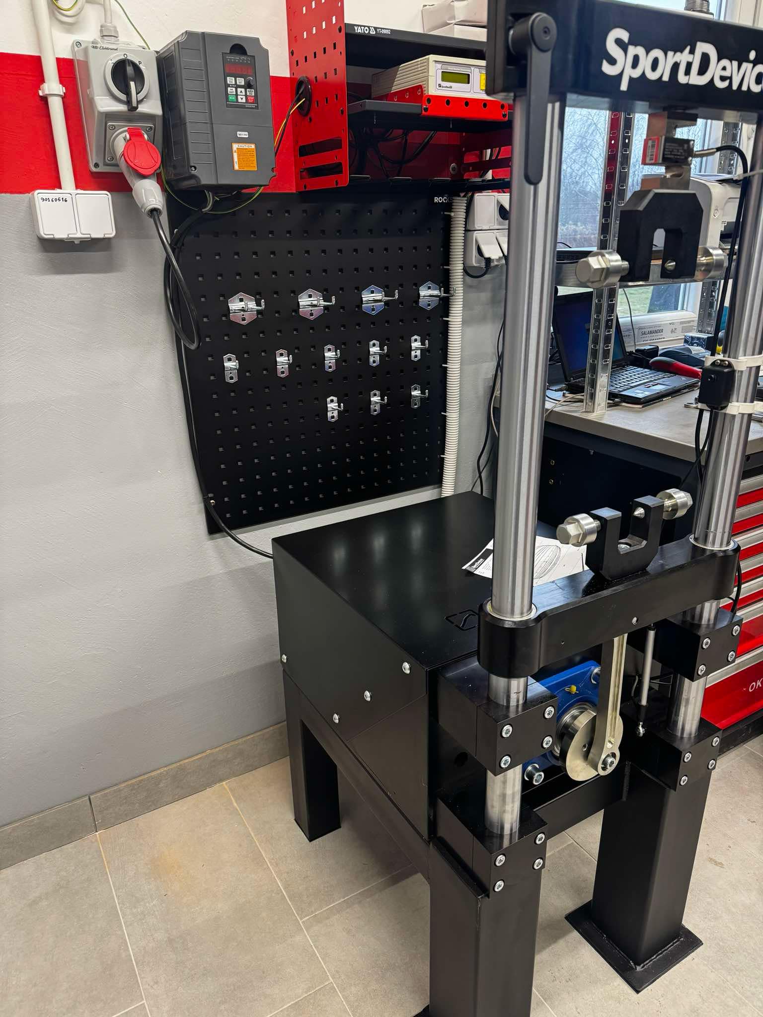
Shock absorber dynos are typically driven by three-phase AC (induction) electric motors. The power and size of the motor are directly dependent on the supply voltage.
It is highly recommended to use an inverter (VFD) that allows automatic multi-speed tests to be performed.
For motors below 4 HP , the inverter can be powered from a single phase (230 V). At higher powers , a three-phase power supply (400 V) is required.
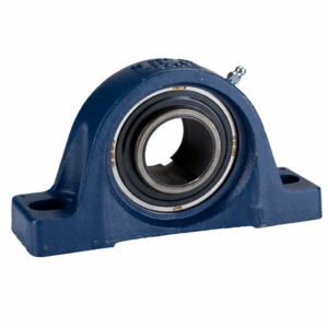
Reduction gearbox
The power output from the motor is transmitted through a reduction gearbox that lowers the rotational speed and increases torque.
The recommended maximum output shaft speed is between 300 and 500 RPM.
It is worth noting that although most induction motors operate at a speed of about 1450 RPM at 50 Hz, the use of an inverter allows you to increase the frequency up to 100 Hz.
This gives:
-
high torque at low speeds (e.g. 300 RPM at the gearbox),
-
the possibility of testing the shock absorber at higher speeds, with only a slight decrease in total power.
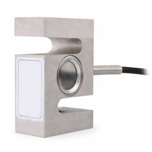
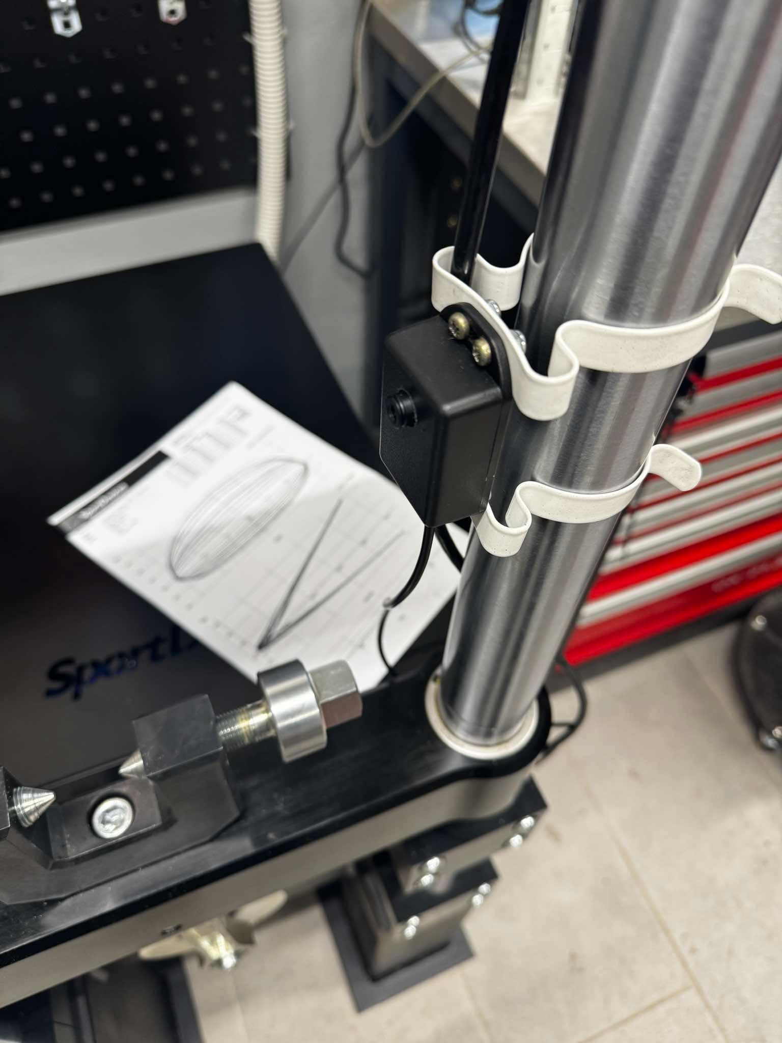
Force Sensor – Strain Gauge (Load Cell)
A force sensor (strain gauge) is a transducer that converts the force acting on it into an analog electrical signal.
Mounted on the dyno’s cross beam, it precisely measures the force generated by the shock absorber during operation, which enables an accurate analysis of the damping characteristics.
Shock Absorber Temperature Sensor
The temperature of the shock absorber is measured by means of a thermocouple, which is attached to the shock absorber body using Velcro.
Shock performance can change drastically with temperature, so controlling it is crucial in professional testing.
With a temperature monitoring system, you can:
-
analyze the behavior of the shock absorber in different conditions,
-
warm up the shock absorber directly on the dyno,
-
simulate real-world working conditions.
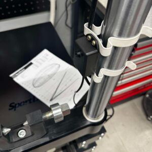
Position potentiometer
The ShockAnalyzer DAQ system uses a 100 mm stroke potentiometer to measure the position and speed of movement of the shock absorber.
This item is included as standard.
A 150 mm potentiometer is also available as an option, allowing you to measure shock absorbers with a longer stroke.
Stroke Length Positions
The system allows you to work in 10 predefined stroke positions, which allows you to precisely adjust the test to different types of shock absorbers.
| Position | Shock absorber travel |
|---|---|
| 1 | 10 mm |
| 2 | 20 mm |
| 3 | 30 mm |
| 4 | 40 mm |
| 5 | 50 mm |
| 6 | 60 mm |
| 7 | 70 mm |
| 8 | 80 mm |
| 9 | 90 mm |
| 10 | 100 mm |
Stroke adjustment range: 10-100 mm
Application: tests of shock absorbers with different strokes, from sports to off-road and custom.
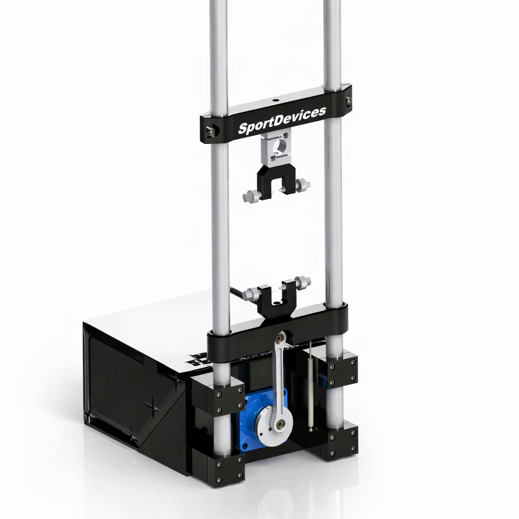
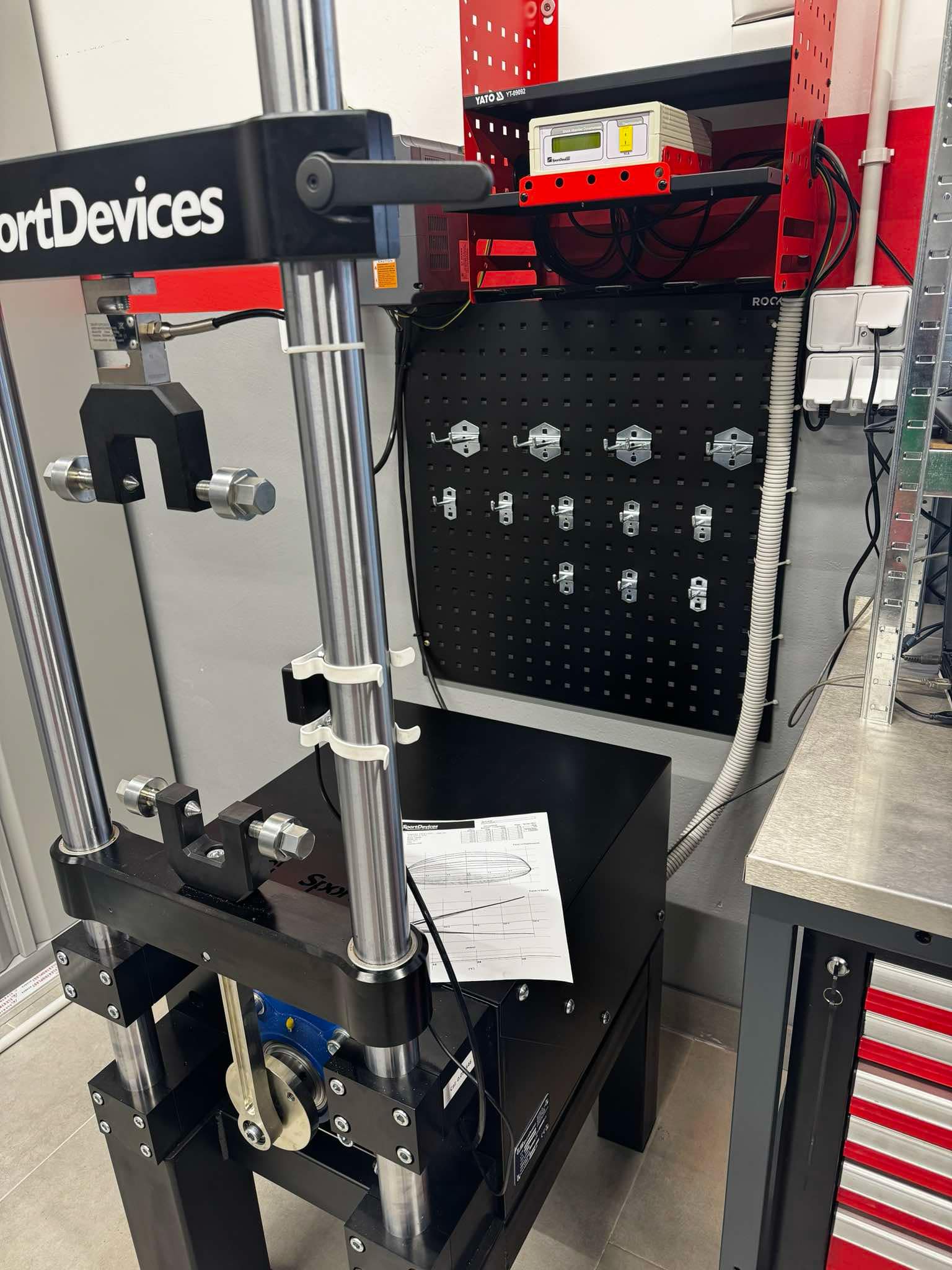
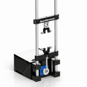
Piston-crank mechanism
The piston-crank mechanism consists of a drum, connecting rod and piston, analogous to the classic system used in internal combustion engines.
The drum has holes that allow you to change the length of the stroke, which allows you to flexibly adjust the operating parameters of the dyno to the tested shock absorber.
Advantages of the piston-crank mechanism:
-
high reliability and durability,
-
lower production costs compared to other solutions,
-
Reduced requirements for precision machining with very tight tolerances.
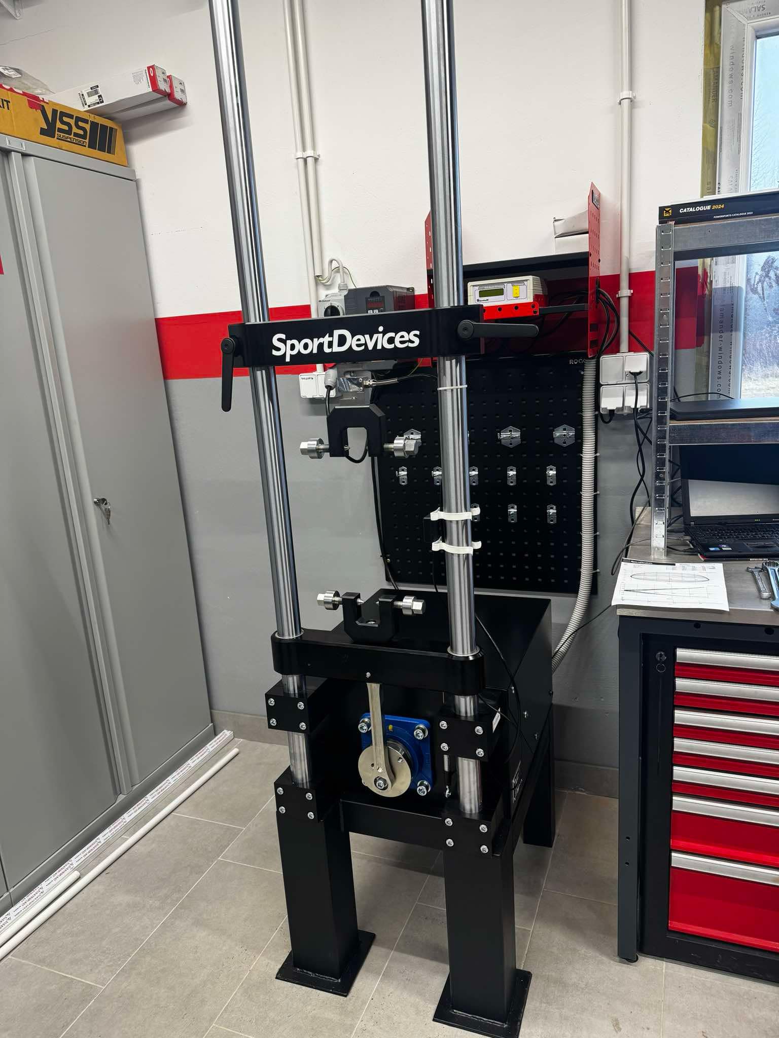
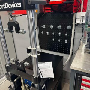
Test Preparation
-
The shock absorber is screwed onto the dyno at dedicated attachment points.
-
The working stroke is selected mechanically on a rotating drum.
-
After changing the stroke, it is necessary to calibrate the speed for the new stroke value.
-
The test table enters:
-
required test speeds,
-
the number of cycles needed for stabilization,
-
the number of cycles dedicated to data logging.
-
Test Flow
-
A “Spring” test is performed, the purpose of which is:
-
determination of the initial offset,
-
determination of the force-position relationship resulting from the presence of gas in the shock absorber
(spring-like effect).
-
-
The actual test is initiated and the motor speed is controlled by an inverter (VFD) according to the values recorded in the test table.
-
The ShockAnalyzer DAQ system transmits all data in real time:
-
location,
-
strength,
-
shock absorber temperature,
that are saved to your computer.
-
-
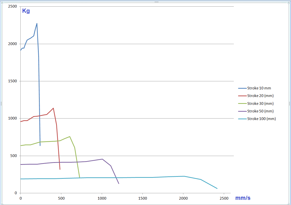
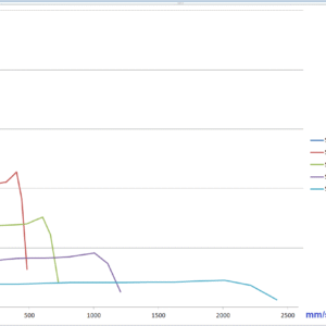
The software displays the collected data in various graphical modes, m.in.:
-
Strength vs Position,
-
Force vs velocity,
-
Force vs Peak Speed,
-
and other analytical charts.
-