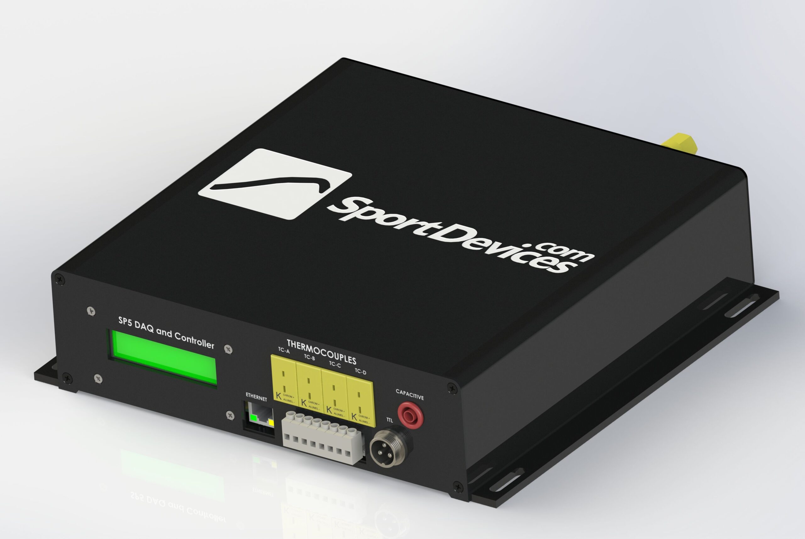

NEW! SP5-AWD – AWD-enabled dynamometer controller (DAQ)
The SP-5 dyno controller provides a complete hardware and software solution for controlling engine test bed and roller dynoes.
The device uses Safety Oriented Closed Loop Brake Control and can work even without a computer connected – control is possible from the remote control.
Available operating modes:
-
Inertial
-
Steady Load
-
Ramp (Ramp)
-
Fixed Brake
Additional modes, such as Road Simulation, are available in the PC software.
SP5-AWD – four-wheel drive version
The new version of the SP5-AWD enables electronic synchronization of the front and rear axles, making it ideal for AWD (4×4) dyno.
The controller also allows the operation of a 2-HUB dyno, where each roller channel controls a separate brake (left and right).
Application
The SP5-AWD is the perfect tool for:
-
engine performance tests,
-
ECU calibration,
-
endurance tests,
-
exhaust emission tests,
-
advanced R&D testing.
Functions and Features
-
Built-in LCD display – makes installation and setup easy
-
High-speed Ethernet connection
-
Control and monitoring of the test engine and brake
-
Remote control of dyno systems from PC, m.in.:
-
throttle actuator,
-
clutch cylinder,
-
gear shifting,
-
cooling fans / blowers
-
-
Dual roller + load cell channels and brake outputs
– support for AWD dyno
– synchronization of rolls
The AWD option requires additional components, such as:
-
additional brake power supply,
-
second force sensor (load cell),
-
additional Hall sensor,
What’s included in the SP5 kit?
-
1 × SP5 Data Acquisition Unit
-
1 × SP5 → PWS Cable Adapter
-
Installation Wire Kit:
-
Hall Sensor Extender
-
serial cable
-
-
1 × USB-to-RS232 adapter with FTDI chip
(Best Compatibility)
AWD version – additional elements
-
Activating the AWD Sync Firmware
-
2. Hall sensor for roller/brake speed measurement
-
2. Force Sensor (Load Cell)
-
2. Brake power supply
Input Specification
-
2 × brake/roller speed input
-
1 × Motor RPM input
– support for capacitive and inductive terminals -
6 × analog inputs (0-5 V)
-
8 × inputs of K-type thermocouples
-
2 × of force sensor input (Load Cell)
– 16/24 bit resolution
– digital zero and gain control -
1 × pulse counter input
(e.g. knock combustion counter) -
1 × RUN/STOP button (as in SP1)
-
*1 × PANIC (Emergency Stop) button
Output Specification
-
2 × PWM Brake Control Signal
-
8 × digital outputs (12V relays)
-
1 × Air Velocity Output
– PWM 0-5V -
1 × servo/throttle output
– 0-5V PWM or RC pulse
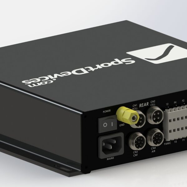
Connectivity and Communication
-
1 × RS232 (DB9)
-
1 × Ethernet (RJ45)
-
1 × CANBUS
– optimized for PWS control
– available free channels for other data
– no license required -
1 × built-in Bluetooth (available on request)
Test and control modes
-
-
Constant RPM (Motor Speed Maintenance)
-
Ramp Test
– programmable inclination -
Sequential / Programmable Test
-
Step Test
-
Road Simulation
(planned in a future version)
-
What does the SP5 kit NOT include?
-
Additional sensors, other than Hall sensor and load cell, m.in.:
-
Lambda sensor
-
Hall sensor for roller/brake speed measurement
- gear with mounting bracket (new version)
-
a set of capacitive and inductive terminals for measuring engine speed (RPM)
-
Force Sensor (Load Cell)
(different ranges available) -
1 × Brake Power Supply
(different voltages and current ranges available) -
Weather Station
-
pressure sensors, etc.
-
-
Additional diagnostic interfaces:
-
OBD II
-
xDS (SDS, HDS, KDS)
-
-
Mechanical and Executive Elements:
-
dyno rollers
-
Electromagnetic brake (Eddy current brake)
-
Relays
-
cooling fans
-
inverters (VFD – Variable Frequency Drive)
-
-
Dyno Frame/Construction